Course Name: Build a Modern Computer from First Principles: From Nand to Tetris (Project-Centered Course)
Instructor: Professor Shimon Schocken, Professor Noam Nisans
Book: The Elements for Computing Systems--Build a Modern Computer from First Principles
Week 1
1 Module 0: Introduction
- One only need to know about 'what' rather than 'how' to do programming
- 'How' is about implementation, since you're only using the computers, you don't need to duplicate it, then you don't need to know how to make it actually happen.
- 'What' is about abstraction, you care about what your program suppose to do, i.e., what will happen for each commands you write.
- For multiple layers of abstraction, we only care about the upmost
layer interface
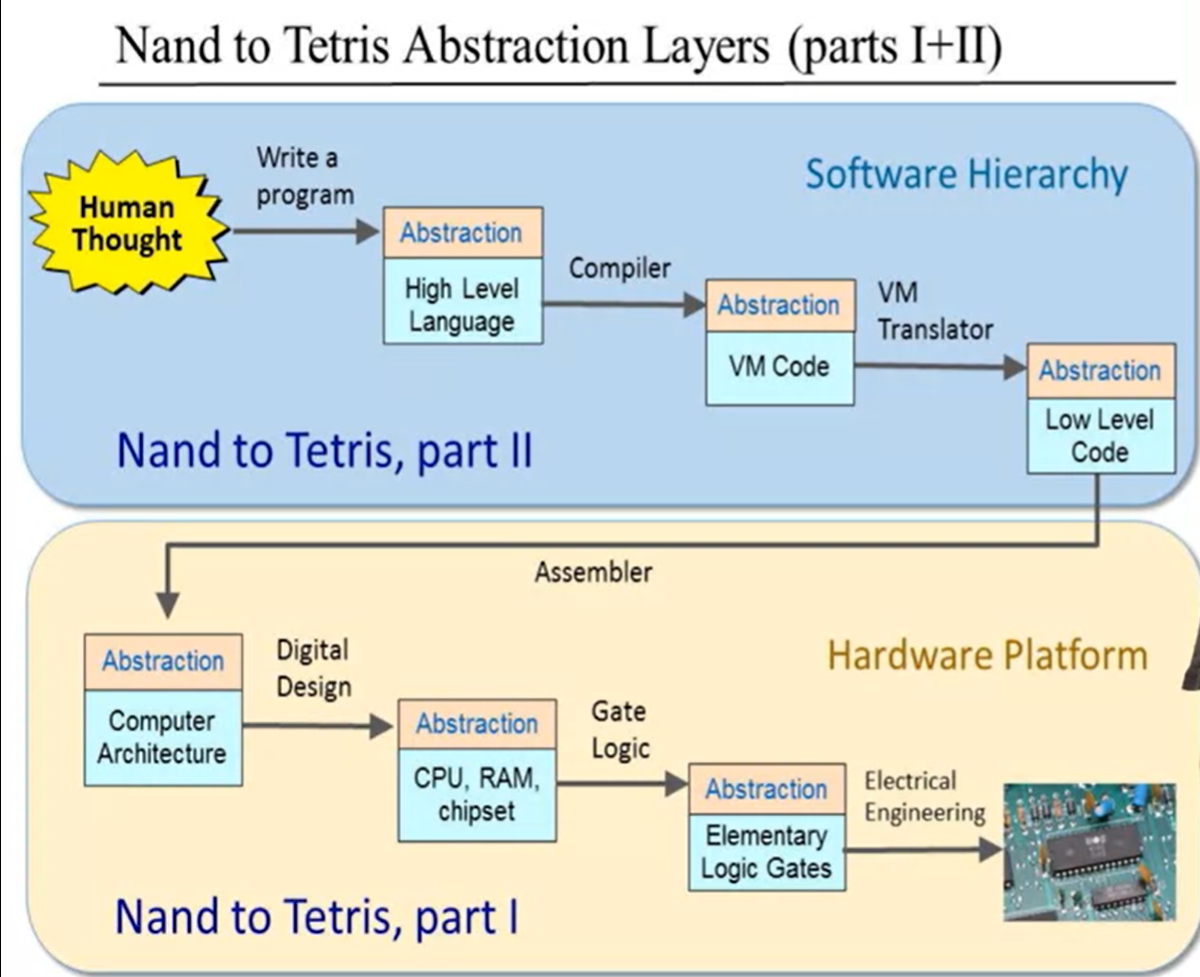
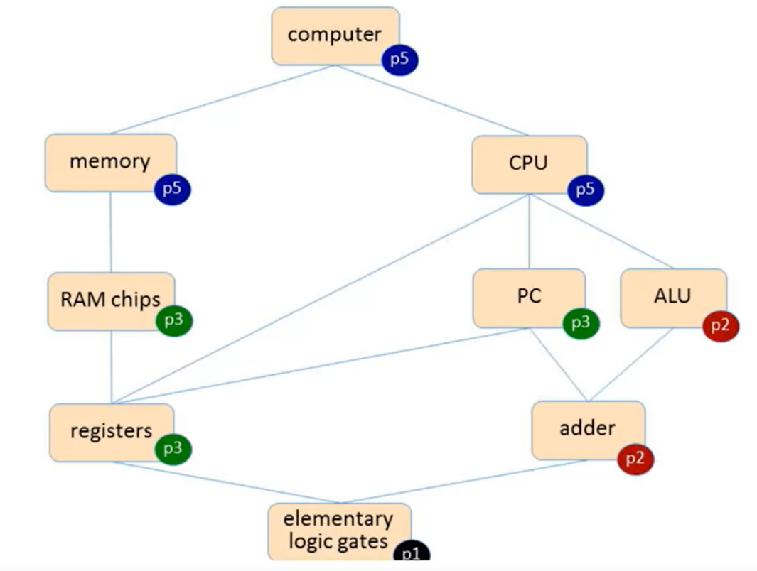
- From Nand to Hack
- The Hack Computer
- Nand is the most elementary logic gate. Other gates like combinatorial logic gates and sequential logic gates are built based on Nand.
- Use hardware simulator to design, test and debug the hardware that one wants to build.
- From Hack to Tetris
- Rich language: expressions, loops, data types, classes, methods
- Built in operations: I/O, Math
- High level language, Complier
- Operating System, Standard Library
2 Module 1: Boolean Functions and Gate Logic
- Boolean Logic
- Boolean operations:
(x AND y)or x \(\land\) y(x OR y)or x \(\lor\) yNOT(x)or \(\neg\) x
- Boolean Functions
- Example:
f(x, y, z) = (x AND y) OR (NOT(X) AND z) - You can also use a truth table to describe a function apart from a formula
- Example:
- Boolean Identities:
(x AND y) = (y AND x)this is a commutative law(x AND (y AND z)) = ((x AND y) AND z)this is an associative law(x AND (y OR z)) = (x AND y) OR (x AND z)this is a distributive lawNOT(x AND y) = NOT(x) OR NOT(y)this is a De Morgan Law
- Boolean operations:
- Boolean Function Synthesis
It's easy to draw a truth table from a boolean function, but the reverse process is actually what a computer does
The way converting a truth table into a boolean function formula is called constructing a disjunctive normal form
Steps:
- Find a function for each row with a value 1, the function should take 1 for the current row and 0 for all other rows
- Use
ORto combine the all found functions - Reduce the combined function to one simple function
Theorem: Any boolean function can be represented using an expression containing
AND, andNOToperations.Proof: `OR` can be replaced with `AND` and `NOT` using De Morgan Law: `(x OR y) = NOT(NOT(x) AND NOT(y))`Nand function:
(x NAND y) = NOT(x AND y)Truth table for Nand:
x y Nand 0 0 1 0 1 1 1 0 1 1 1 0 Theorem: Any boolean function can be represented using only
NANDoperations.
Proof:
NOT(x) = (x NAND x)`(x AND y) = NOT(x NAND y)` Since `AND` and `NOT` can be represented by `NAND`, according to the previous theorem, any boolean functions then can be represented using `NAND`
- Logic Gates
- A logic gate is an idealized model of computation or physical electronic device implementing a boolean function. An ideal logic gate has zero rise time and unlimited fan-out, a non-ideal physical device is also a logic gate.
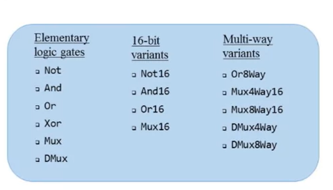
- Elementary logic gate:
NAND - Other elementary logic gate:
AND,OR,NOT - Composite gates:
- Example: a gate
(x AND y AND c)can be regarded as a two step gate,(x AND y)and then((x AND y) ANd c), the order of inputs doesn't change the result
- Example: a gate
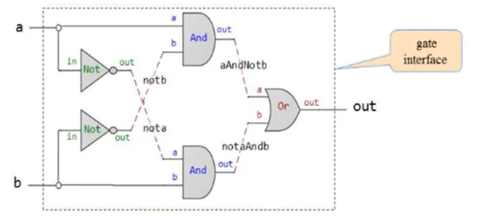
- Gate interface answers the question 'What', gate implementation
answers the question 'How'. In this sense, gate interface is unique,
since there is only one way to describe what the gate is supposed to do,
but there may be multiple implementations that realize the gate
interface abstraction.
- Example: circuit implementations with light bulbs
- Hardware Description Language(HDL)
Example:
Xorgate:- Gate interface:
- Implementation:
1
2
3
4
5
6
7
8
9
10
11
12
/**Xor gate: out = (a And Not(b)) OR (Not(a) And b) */
CHIP Xor {
IN a, b;
OUT out;
}
PARTS:
Not(in = a, out = nota);
Not(int = b, out = notb);
And(a = a, b = notb; out = aAndNotb);
And(a = nota, b = b, out = notaAndb);
Or(a = aAndNotb, b = notaAndb, out = out);
- Gate interface:
HDL definition of a chip consists of a header section and a parts section. The header section specifies the chip interface, namely the chip name and the names of its input and output pins. The parts section describes the names and topology of all the lower-level parts from which this chip is constructed, each part is represented by a statement that specifies the part name and the way it is connected to other parts in the design.
HDL is a functional/declarative language
The order of HDL statement is insignificant
Before using a chip part, one must know its interface
Connections of names are common
- HDL languages: VHDL, Verilog, etc
- Hardware Simulation
- Interactive simulation: the simulator only uses the HDL file
- Script-based simulation: the simulator uses both the HDL file and the test script
- With/without output and compare files: one can compare the output file with a compare file
- Hardware construction projects:
- System architects: decides which chips are needed, for each chip, creates the API, the test script and the compare file
- Developers: given the resources, build the chips using hdl
- Multi-bit Buses
- Sometimes, manipulate together an array of bits is technically convenient, such a group of bits as a single entity is termed 'bus'
- In HDL, there are some chips handling buses that bring much convenience and efficiency
- Sub-bus:
- Syntax:
a[16],a[0..7] = lsb; a[8..15] = msb; - Overlaps of sub-buses are allowed on output busses of parts
- Width of internal pins is deduced automatically
false(all 0s)andtrue(all 1s)may be used as busses of any width
- Syntax:
- Project 1
- Recommended chip-building procedure:
- Recommended chip-building procedure:
Week 2
- Binary Numbers
- For \(N\) bits, there are \(2 ^N\) possible binary numbers
- Convert a binary number to decimal number: \(\sum\limits_{k=0}^{n} {2^k}\), where \(k \in \{0, 1\}\)
- Convert a decimal number to decimal number: \(\sum\limits_{t=0}^{n} {2^{k_t}} = Number\), then binary representation of the decimal number is: \({k_n}...{k_0}\)
- LSB(least significant number): the right-most bit in the binary representation of a number, a.k.a., hight-order bit
- MSB(most significant number): the left-most bit in the binary representation of a number, a.k.a., low-order bit
- Usually the MSB is used for sign, i.e.,
MSB = 0means a positive number,MSB = 1means a negative number
- Binary Addition
If \(sum < 2, \; position \; result = sum\),
if \(sum \geq 2, \; position \; result = sum \;\%\; 2,\; next \; position \; carry = 1\)
Overflow problem: since the computer has limited word size(the amount of bits to hold a number), if the calculation is beyond that, then the result is truncated in the following way: \(\; result = result \;\%\; word \; size\), where \(word \; size = 2^{N-1}\), since MSB is used for the sign of a number
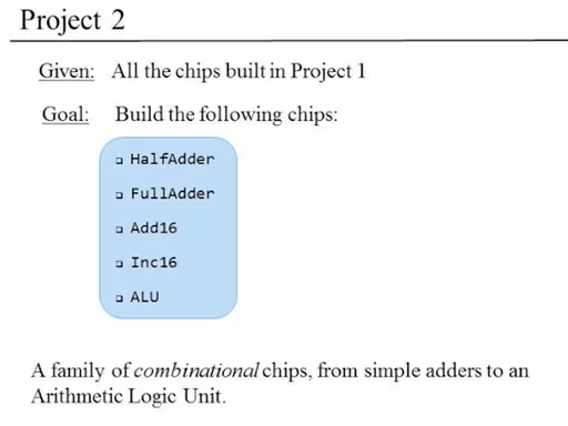
Half adder: add two bits without considering possible position carry
Full adder: add two bits with position carry taken into consideration
Adder: add two numbers
- Negative numbers
- Sign bit: if one uses this representation, then
1000should not be -0, it should be -8. In this way, given the total word size \(N\), the range is \([0, 2^{N-1}-1] \; and \; [-2^{N-1}, -1]\) - 2's Complement: the binary representation for \(-K\) is the binary representation for \(2^{N} - K\), given the total word size
\(N\). In this way, the range is also
\([0, 2^{N-1}-1] \; and \; [-2^{N-1},
-1]\)
- There is truncation for \(2^{N} - K\) if the binary representation is beyond the word size \(N\)
- Compute \(-X\): then wen can compute \(x - y\) by using \(x + (-y)\)
- Sign bit: if one uses this representation, then
- Arithmetic Logic Unit(ALU)
- Von Neumann Architecture:
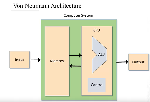
- The ALU computes a function on two inputs, and outputs the result. The function includes a family of pre-defined arithmetic and logical functions.
- The Hack ALU:
- Two 16-bit, 2's complement inputs, one 16-bit, 2's complement output
- One function selected using 6 1-bit inputs from a 18-function
family. The 6 1-bit inputs are:
zx: ifzx = 1, thenx = 0nx: ifnx = 1, thenx = !xzy: ifzy = 1, theny = 0ny: ifny = 1, theny = !yf: iff = 1, thenout = x + y, iff = 0, thenout = x & yno: ifno = 1, thenout = !out
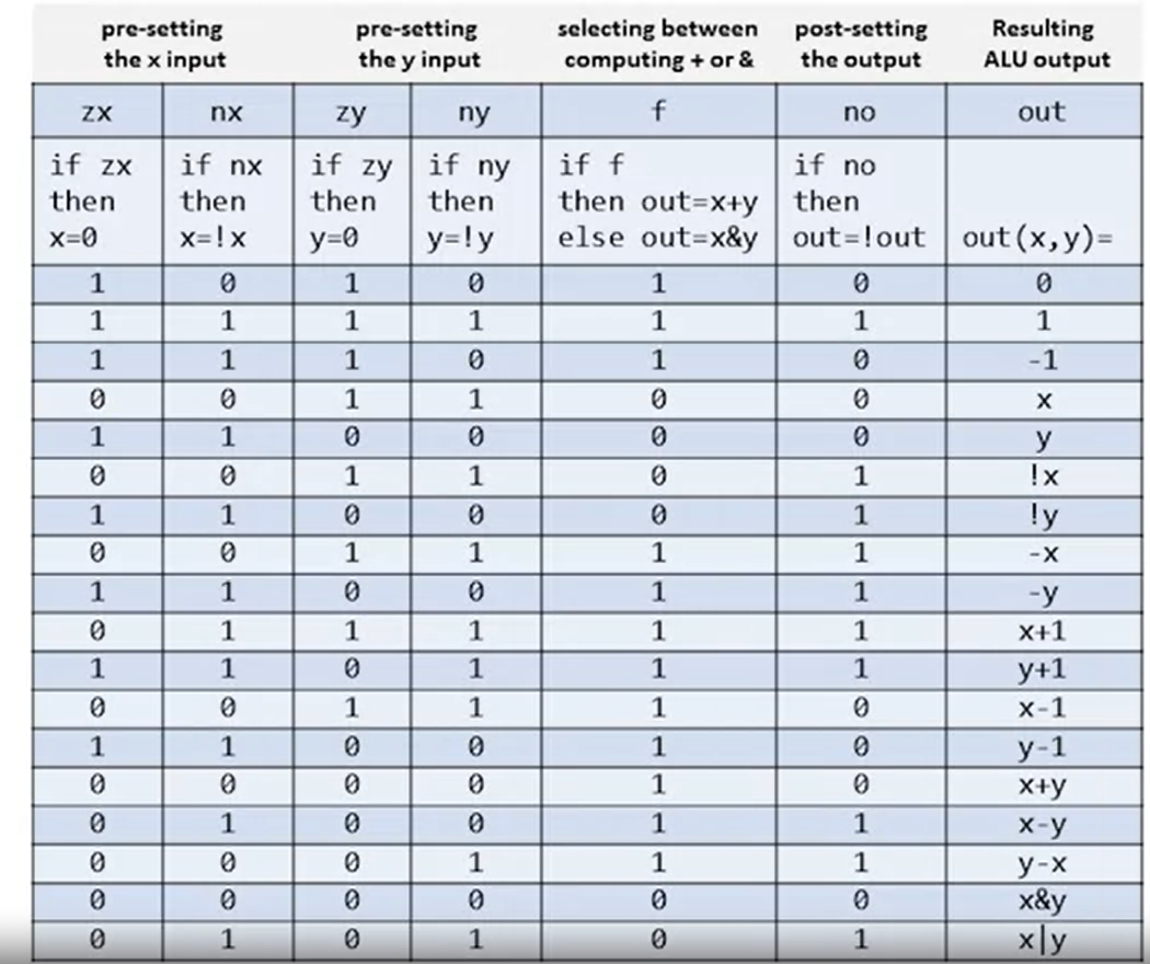
- Also two 1-bit outputs:
zr: ifout == 0, thenzr = 1, elsezr = 0(You can checkout[k] == 0for every k usingOR)ng: ifout < 0, thenng = 1, elseng = 0(You can check ifout[MSB] == 1)
- The hack ALU is simple, elegant and easy to implement
- Von Neumann Architecture:
- Project 2
Week 3
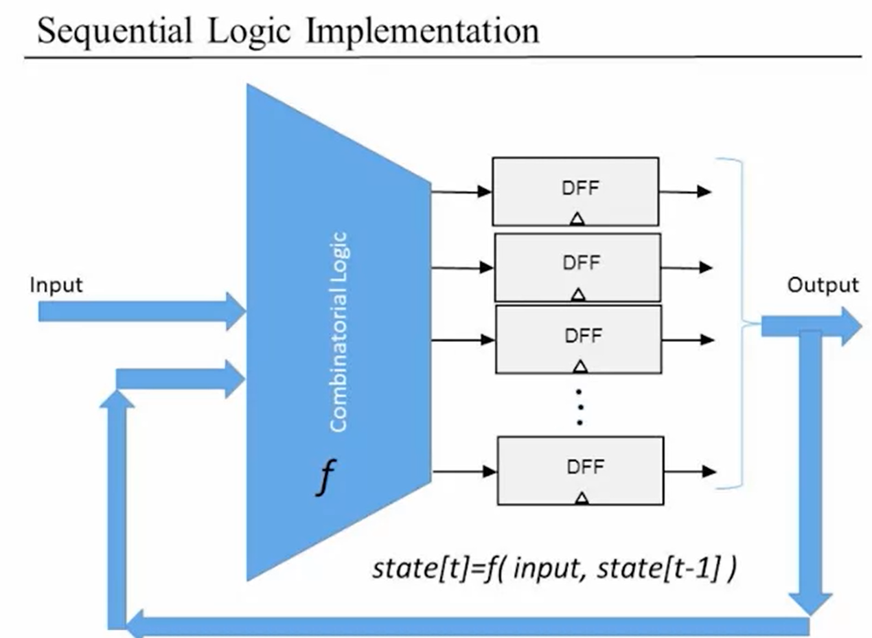
- Sequential Logic
- Combinatorial logic ignores time, everything happens immediate at the same time
- Use integer time unit to represent the pass of time, each time unit has its own input and output
- Ideally, the input occurs at the beginning of each unit, the output occurs at the ending of each unit, both instantaneously. However, there are some delays in reality(time for voltage changes, time for gate delay itself, etc.), it's quite necessary that the integer time unit is set a little bit wider to take the delays into consideration.
- Mathematical representation:
- Combinatorial logic: \(\; out[t] = function(in[t])\)
- Sequential logic: \(\; out[t] = function(in[t - 1])\), since there is a delay from input to output, then we can simply use one variable called state instead, i.e., \(\; state[t] = function(state[t - 1])\)
- Flip Flops
- Gates that can flip between states are called flip flops(触发器)
- The Clocked Data Flip Flop:
out[t] = in[t - 1]- It's primitive for this course, but actually it can be built from
the
Nandchip - Sequential logic implementation:
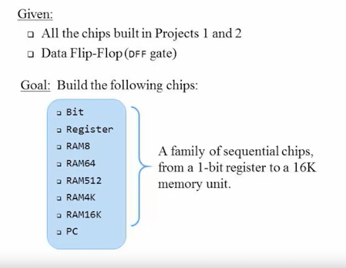
- 1-big Register: remembers an input forever until requested to load a
new value
- If the load bit exists, outputs last input, if the load bit perishes, outputs last output
- Use a
Muxand a `DFF to construct the 1-bit register
- Memory Units
Categories:
- Main memory: RAM, ...
- Secondary memory: disks, ...
- Volatile/non-volatile memory: whether the stored data persists when the electricity power is cut off. RAM is volatile and disk is non-volatile.
The most basic memory element: Register:
- Put multiple 1-bit register together to form a multi-bit register, the word size may be 16-bit, 32-bit, 64-bit
- State: the value that is currently stored in the register
- From the output of the register, one can know the state of the
register:
1
2
3
4
5
6
7
To set register state = v:
set in[t] = v,
set load[t] = 1.
Then,
state[t + k] = v,
out[t + k] = v, for any k unless a new load is set to 1.
RAM unit:
- RAM Unit:
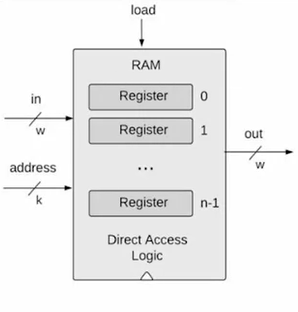
- RAM(random access memory): irrespective of the RAM size, every register can be accessed at the same instantaneous time
- RAM abstraction: a sequence of n addressable registers, with addresses 0 to n-1
- At any given point of time, only one register is the RAM is selected
- Width of address input k: \(k = log_2n\). Though I think \(k = [log_2n] + 1\) here is better.
- Width of word: No impact on the RAM logic. For Hack computer, \(w = 16\).
- RAM is a sequential chip, with a clocked behavior
- RAM Unit:
Steps for RAM Read Logic:
- Set
address = k - Read the out of the register unit, then we can know the state of the selected kth register
- Set
Steps for RAM Write Logic:
- Set
address = k - Set
in = v - Set
load = 1 - The the state of the register becomes v and from the next cycle
onward,
out = vfor the RAM unit
- Set
A family of 16-bit RAM chips:
chip name n k RAM8 8 3 RAM64 64 6 RAM512 512 9 RAM4K 4096 12 RAM16K 16384 14
- Counters
- The computer must keep track of which instruction should be fetched and executed next, this control mechanism can be realized using a program counter. The PC contains the address of the instruction that will be fetched and executed next.
- Three possible control settings:
- Reset: fetch the first instruction
PC = 0 - Next: fetch the next instruction
PC++ - Goto: fetch instruction n
- Reset: fetch the first instruction
- Counter abstraction:
- Program Counter:
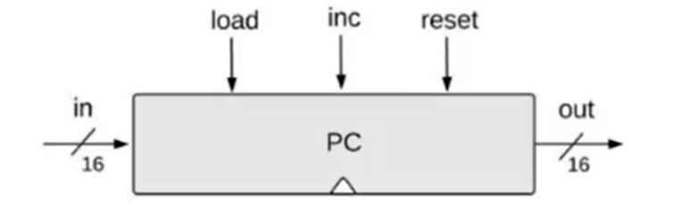
- If
reset[t] == 1,out[t + 1] = 0, resets counter to 0 - If
load[t] == 1,out[t + 1] = in[t], sets counter = value - If
inc[t] == 1,out[t + 1] = out[t] + 1, increments counter by 1 - Else
out[t + 1] = out[t], nothing changes
- Program Counter:
- Project 3
Week 4
- Machine Languages: Overview
- Theoretical universal turing machine: one machine can do many tasks. Actual general computing machine: von Neumann Architecture
- Compilation: high-level language => Compiler => machine language => CPU
- Assembler can translate assembly language into machine language
- Machine Languages: Elements
- Machine language specifies the hardware/software interface, it's usually in close correspondence to actual hardware architecture, and as is often the case, the more operations supported by a machine language, the more sophisticated the machine language is
- Machine Operations:
- Arithmetic operations: add, subtract, ...
- Logical operations: and, or, ...
- Flow control: goto, if then goto, ...
- Addressing:
- Accessing a memory location is expensive, because it needs to supply a long address and getting the memory contents into the CPU also takes time
- Solution to the above problem is memory hierarchy: register => cache => main memory => disk. The closer to CPU, the smaller in size of the memory.
- Data Registers: Add R1, R2; Address Registers: Store R1, @A
- Addressing modes: register, direct, indirect, immediate
- Input/Output:
- Devices: keyboard, mouse, camera, sensor, printer, screen, ...
- CPU needs protocol to talk to them. Software drivers know the protocols. An general method of interaction uses memory mapping
- Flow Control:
- Usually CPU executes machine instructions in sequence, sometimes we need jump to somewhere. There is both unconditional jump and conditional jump.
- The Hack Computer and Machine Language
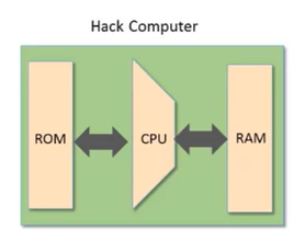
- Hack Computer Hardware:
- Data memory(RAM): a sequence of 16-bit registers
- Instruction memory(ROM): a sequence of 16-bit registers
- Central Processing Unit(CPU): performs 16-bit instructions
- Instruction bus/data bus/address buses
- Hack Computer Software:
- Hack machine language:16-bit A-instructions, 16-bit C-instructions
- Hack program: sequence of instructions written in the Hack machine language
- Control:
- The ROM is loaded with a Hack program
- The reset button is pushed
- The program starts running
- Registers:
- D register in CPU: holds a 16-bit value of data
- A register in CPU: holds a 16-bit value of data or address
- M register in RAM: represents the 16-bit RAM register addressed by
A,
M = RAM[A]
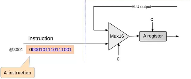
- The A-instruction:
- Syntax:
@value, a value is a non-negative decimal constant or a symbol referring to such a constant - Meaning: sets the A register to value,
RAM[A]becomes the selected RAM register M
- Syntax:
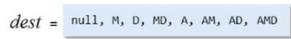
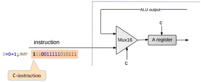
- The C-instruction:
dest = comp; jump(both dest and jump are optional)

- Meaning: computes the value of
comp, stores the result indest, if the boolean expression(comp jump 0)is true, jumps to execute the instruction stored inROM[A]1
2
3
4
5
6
7
8
9
10
11// Set the D register to -1
D = -1
//Set RAM[300] to the value of the D register minus 1
@300 //A = 300
M = D - 1 // R[300] = D - 1
// If (D - 1 == 0) jump to execute the instruction stored in ROM[56]
@56 //A = 56
D - 1;JEQ //if(D - 1 == 0) goto 56
- Hack Computer Hardware:
- Hack Language Specification
- Two ways to express the same expression:
- Binary code
- Symbolic language
- The A-instruction:
- Symbolic syntax:
@ value, value is a non-negative decimal constant \(\leq 2^{15} - 1\) or a symbol referring to such a constant - Binary syntax:
0 value, value is a 15-bit binary number
- Symbolic syntax:
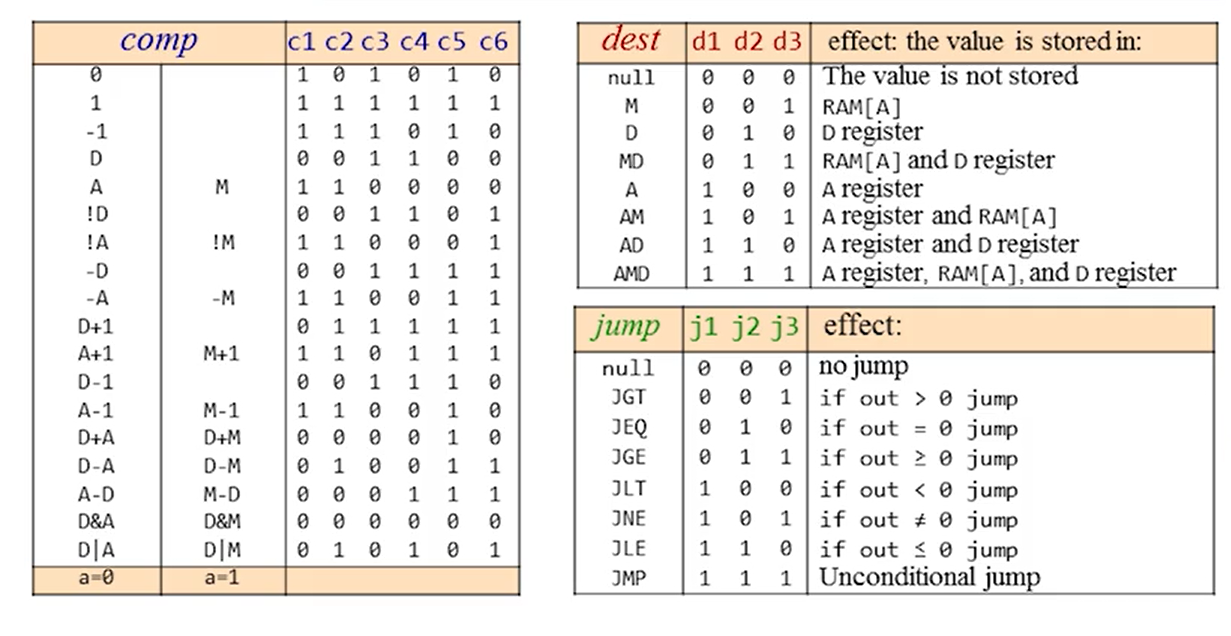
- The C-instruction:
- Symbolic syntax:
dest = comp; jump - Binary syntax:
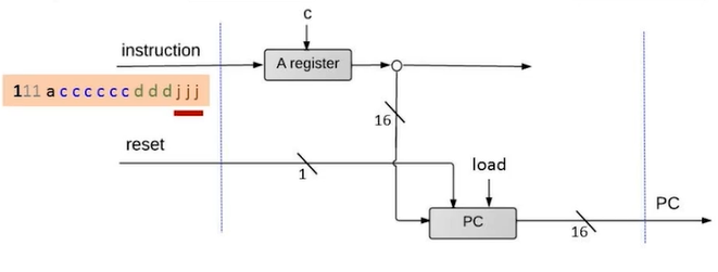
1 1 1 a c1 c2 c3 c4 c5 c6 d1 d2 d3 j1 j2 j3- The first
1: the op code for c-instruction - The second and third
1: not used a c1 c2 c3 c4 c5 c6: comp bitsd1 d2 d3: dest bitsj1 j2 j3: jump bits
- The first
- Symbolic syntax:
- Two ways to express the same expression:
- Input/Output
- Peripheral I/O devices:
- Keyboard: used to enter inputs
- Screen: used to display outputs
- High-level approach: sophisticated software libraries enabling text, graphics, animation, audio, video, etc.
- Low-level: bits
- Output Using Screen Memory Map:
- A screen memory map is a designated memory area in RAM, it's dedicated to manage a display unit. The physical unit is refreshed many times per second.
- The screen memory map is a sequence of 16-bit values(each value is called a word) with length of 8192. And the display unit is a 256 by 512(b/w) table, each element is a pixel that can be turned on or off. So each bit is matched with a pixel. (\(16 * 8192 = 256 * 512\)). Each 32 rows in the screen memory map is mapped to one row in the physical display unit. ($16 * 32 = 512 $)
- Set the
(row, col)pixel on/off:- Find the word: the word should be at
32 * row + col /16(here / is integer division) in the memory map. If the first word(indexed with 0) is atRAM[n], the the target word is atRAM[n + 32 * row + col / 16]. - Find the bit: in the word, the bit is at
col % 16, set the bit to 0/1. - Commit the change to RAM
- Find the word: the word should be at
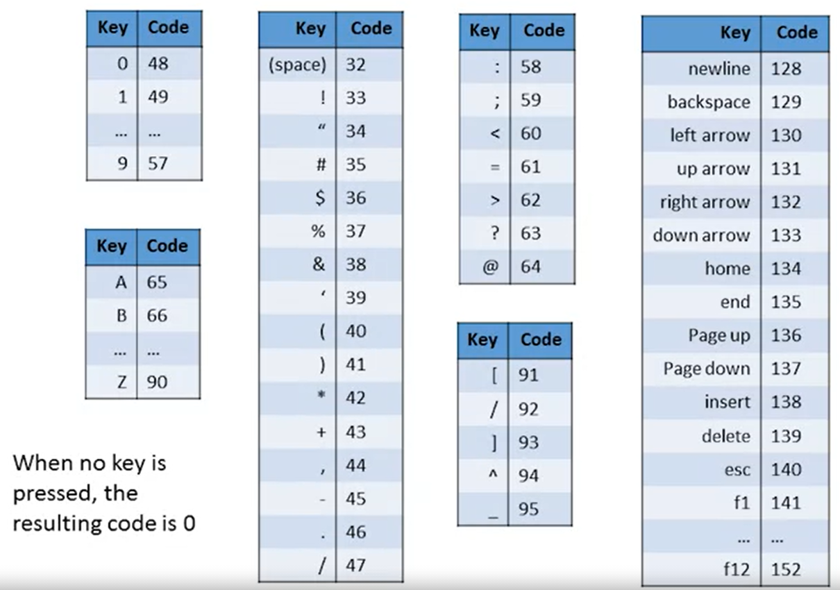
- Input Using Keyboard Memory Map:
- A keyboard memory map is a single 16-bit register called keyboard in RAM, it can manage a physical keyboard.
- When a key is pressed, its scan code appears in the keyboard memory map as a 16-bit value.
- Check which key is currently pressed:
- Probe the contents of the keyboard chip.
- In the Hack computer, probe the contents of
RAM[24576]. If the register contains 0, no key is pressed at present.
- Peripheral I/O devices:
- Hack Programming
- Working with registers and memory
- Basics:
1
2
3
4
5
6
7
8
9
10
11
12
13
14
15
16
17
18
19
20
21
22
23
24
25
26// D = 10
@ 10 // Set A to 10
D = A
// D ++
D = D + 1
// D = RAM[17]
@ 17 // Select the register at RAM[17]
D = M
// RAM[17] = D
@ 17
M = D
// RAM[17] = 10
@ 10
D = A // Acquire the constant and store into D
@ 17
M = D
// RAM[5] = RAM[3]
@ 3
D = M // Acquire the value and store into D
@ 5
M = D - Example : add two numbers
1
2
3
4
5
6
7// RAM[2] = RAM[0] + RAM[1]
@ 0
D = M // D = RAM[0]
@ 1
D = D + M // D = D + RAM[1]
@ 2
M = D // RAM[2] = D - Terminate a program properly
- The above program is not safe, because it doesn't end properly. Someone could add malicious code after the above code to do something bad or dangerous, this is called NOP slide. NOP slide is a sequence of NOP(non-operational) instructions intended to slide the CPU's instruction execution flow to its final, desired destination whenever the program branches to a memory address anywhere on the slide.
- One can add an infinite loop to end a program:
1
2@ value
0; JMP
- Built-in symbols:
- Symbol
Rnhas valuenfor n in 0, ... ,15. Use these symbols rather than numbers when referring the first 16 registers in your code so it's more readable. SCREENhas value 16384, used for screen outputKBDhas value 24576, used for keyboard inputSPhas value 0LCLhas value 1ARGhas value 2THIShas value 3THAThas value 4
- Symbol
- Basics:
- Branching
- Definition: evaluate a boolean expression and go to different sections afterwards based on the result. There is only one branching apparatus in machine language called goto.
- Example:
- Original code:
1
2
3
4
5
6
7
8
9
10
11
12
13
14
15
16
17
18
19
20// if R0 > 0
R1 = 1
else
R1 = 0
@ R0
D = M // D = RAM[0]
@ 17
D; JET // if R0 > 0, goto 17
@ R1
M = 0 // R[1] = 0
@ 19
0; JMP // end of program
@ R1
M = 1 // R[1] = 1
@ 19
0; JMP // end of program - Labeled code:
1
2
3
4
5
6
7
8
9
10
11
12
13
14
15
16
17
18
19
20
21
22
23
24// if R0 > 0
R1 = 1
else
R1 = 0
@ R0
D = M
@ POSITIVE // Use a label, it equals to @ n, n is the instruction number following the (label) declaration. Here equals to @ 18
D; JET
@ R1
M = 0 // R[1] = 0
@ END // Use a label, here equals to @ 22
0; JMP
(POSITIVE) // Declare a label, label declaration is not translated into machine code, it's like a placeholder
@ R1
M = 1
(END)
@ END
0; JMP
- Original code:
- Variables
- A variable is a container that has a name and a value. In hack language, there is only one variable type, the 16-bit values.
- Example
1
2
3
4
5
6
7
8
9
10
11
12
13
14
15
16
17
18
19
20
21
22
23// Exchange the values of RAM[0] and RAM[1]
// temp = R1
// R1 = R0
// R0 = temp
@ R1
D = M
@ temp // Find an available memory register(say register n), use it to represent the variable temp. From now on, @ temp equals to @ n.
M = D
@ R0
D = M
@ R1
M = D
@ temp
D = M
@ R0
M = D
(END)
@ END
0; JMP
- Iteration
- Example:
1
2
3
4
5
6
7
8
9
10
11
12
13
14
15
16
17
18
19
20
21
22
23
24
25
26
27
28
29
30
31
32
33
34
35
36
37
38
39// Computer RAM[1] = 1 + 2 + ... + n
// Put a number (n) in RAM[0]
@ R0
D = M
@ n
M = D //n = R0
@ i
M = 1 // i = 1
@ sum
M = 0 // sum = 0
(LOOP)
@ i
D = M
@ n
D = D - M
@STOP
D; JGT // if i > n goto STOP
@ sum
D = M
@ i
D = D + M
@ sum
M = D // sum = sum + i
@ i
M = M + 1 // i = i + 1
@ LOOP
0; JMP
(STOP)
@ sum
D = M
@ R1
M = D // RAM[1] = sum
(END)
@ END
0; JMP - Best practices:
- Design your program using pseudo code
- Write the program in an assembly language
- Test the program using a variable-value trace table
- Example:
- Pointers
- For an array, memory stores its start address and the length
- Variables that store memory addresses are called pointers
- Hack pointer logic: whenever we have to access memory using a
pointer, we need an instruction like
A = M, which sets the address register to the content of a memory register
- Input/Output
- Hack RAM:
- 0-16383: 16k data memory
- 16384-24575: 8k screen memory map
- 26576: keyboard
- Hack RAM:
- Working with registers and memory
- Project 4
Week 5
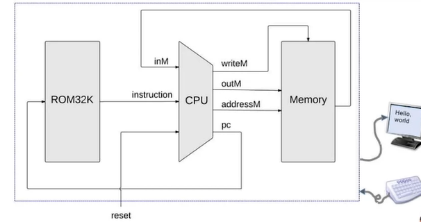
- Von Neumann Architecture
- The architecture:
- CPU: ALU, registers
- Memory: data memory, program memory
- Wire/bus: data wires, address wires, control wires
- ALU wires:
- Data wires: get data and output data
- Control wires: get executions and tell other parts what to do
- Register wires:
- Data wires: get dat and output data
- Address wires: some registers can specify addresses
- Memory wires:
- Address wires: specify memory addresses
- Data wires: input and output data
- Control wires: interact with executions in the program memory
- The architecture:
- The Fetch-Execute Cycle
- Fetch: fetch an instruction from the program memory
- Put the location of the next instruction into the address of the memory using program counter
- Get the instruction code itself by reading the memory contents at the location
- Execute: execute the instruction from the fetch part
- Put the instruction bits into control wires and tell other parts what to do
- Executing procedure also involves accessing data memory
- A problem: in the fetch process, we need to put into the memory the
instruction, but in the execute process, we need to put into the memory
the data. If there is only one memory for both data and program, in
order to avoid the clash, we need to use a multiplexer.
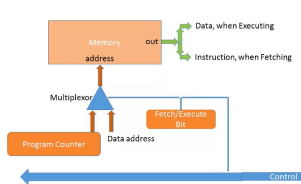
- Simpler solution: Harvard Architecture
- A variant of Von Neumann Architecture
- Keep program and data in two separate memory modules so complication is avoided
- Fetch: fetch an instruction from the program memory
- Central Processing Unit
- The abstraction: a 16-bit processor, designed to execute the current instruction and figure out which instruction to execute next
- Hack CPU interface:
- Inputs: data value, instruction, reset bit
- Outputs: data value, data value write memory address(where to write), load bit(write to memory, yes or no), pc(address of next instruction)
- Hack CPU implementation
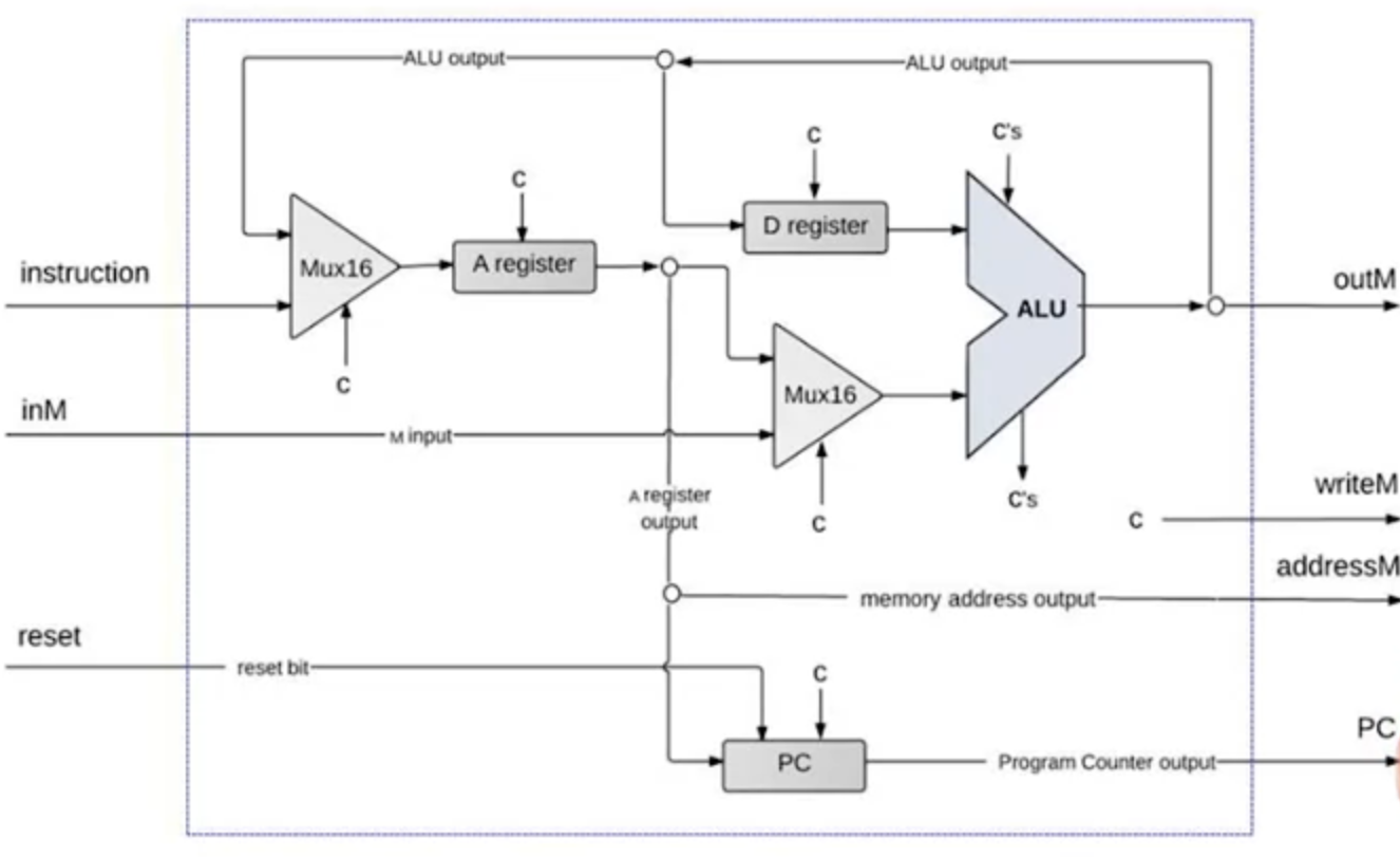
- Instruction handling:
- Handling A instruction:
- Decodes the instruction into op-code + 15-bit value
- Stores the value in the A register
- Outputs the value
- Handling C instruction:
- Decodes the instruction into Op-code, ALU control bits, Destination load bits and Jump bits
- Use the different fields in later steps
- Handling A instruction:
- ALU operations:
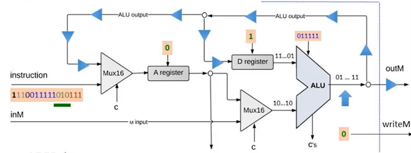
- Data inputs: from the D register , from the A register/M register
- Control inputs: control bits from the instruction
- ALU data outputs: result of ALU calculation, fed simultaneously to D register, A register and M register. The three destination bits determine which register actually receive the incoming value.
- Control:
- Reset is used to start a loaded program
- PC:
- Emits the address of the next instruction.
- To start/restart the program's execution:
PC = 0. - No jump:
PC++ - Goto:
PC = A - Conditional goto:
if true then PC = A else PC++ - PC logic:
1
2
3
4
5
6
7
8
9
10
11if (reset == 1) {
PC = 0;
} else {
// current instruction code
load = f(jump bits, ALU control outputs);
if (load == 1) {
PC = A;
} else {
PC ++;
}
}
- Reset is used to start a loaded program
- The Hack Computer
- Abstraction: it's a computer that is capable of running programs written in the Hack machine language. It's built upon the Hack chip set.
- Hack CPU operation: executes instruction according to the Hack
language specification
- If includes D and A then read from/write into D register and A register
- If include @ x, then x is stored into A register and value is emitted by M register
- If RHS includes M, then value is read from M
- If LHS includes M, then ALU output is emitted by M
- Data Memory(RAM):
- Address 0 to 16383 is data memory, RAM is implemented using a 16-bit 16K RAM chip
- Address 16384 to 24575 is screen memory map, screen is implemented using a built-in 8K chip featuring a raster display refresh side-effect
- Address 24576 is keyboard memory map, keyboard is implemented using a built-in chip featuring a keyboard capture side-effect
- Reset button
- Instruction Memory(ROM)
- Implemented using the ROM32K chip
- Run a program on the Hack computer:
- Load the program into the ROM using plug-and-play ROM chips or using hardware simulation with text-file programs
- Press reset button
- The program starts running
- Project 5
- Hardware Projects:
- Hardware Projects:
Week 6
- Assembly Languages and Assemblers
- Assembly language program => Assembler => Machine language program => Hack computer
- Basic assembler logic:
- Repeat:
- Read the next assembly language command, i.e., read next line ignoring whitespace
- Break it into the different fields of which it is composed
- Lookup the binary code for each field
- Combine theses codes into a single machine language command
- Output this machine language command
- Until EOF reached
- Symbols should be replaced with their addresses in the program, so
the assembler needs to maintain a symbol-address table.
- For a variable, add it to the table if it is not in the label, otherwise simply look it up in the table
- For a label, it could use forward reference, which means one can refer to a label before it is declared. There are two ways to deal with forward reference, the first is to leave blank until label declaration appears and then fix; the second is run the program for 2 times, add each label into the table for the first pass, and run other parts for the second pass.
- Repeat:
- The Hack Assembly Language
- Language:
- A-instruction
- C-instruction
- Symbols
- Assembler:
- Basic one: translate symbol-less Hack program
- Advanced one: able to handle symbols
- Language:
- The Assembly Process-Handling Instructions
- Translating A-instructions
@ value- If the value is a decimal constant, generate the equivalent 15-bit binary constant
- If the value is a symbol, later in the advanced assembler
- Translating C-instructions
dest = comp; jump- The binary form is simply
1 1 1 a c1 c2 c3 c4 c5 c6 d1 d2 d3 j1 j2 j3
- The binary form is simply
- The overall assembly logic:
- For each instruction:
- Parse the instruction: break it into its underlying fields
- A-instruction: translate the decimal value into a binary value
- C-instruction: for each field in the instruction, generate the corresponding binary code
- Assemble the translated binary codes into a complete 16-bit machine instruction
- Write the 16-bit instruction to the output file
- For each instruction:
- Translating A-instructions
- The Assembly Processing-Handling Symbols
- Symbols:
- Variable symbols: represent memory locations where the programmer wants to maintain values
- Label symbols: represent destinations of goto instructions
- Pre-defined symbols: represent special memory locations
- Pre-defined symbols:
- Hack language has 23 pre-defined symbols that are only used in A-instructions
- Simply replace the symbols with is values
- Label Symbols:
- Replace the symbols with the address next to is declaration
- Variable Symbols:
- A symbol that is not a pre-defined symbol and not a label is called a variable, each variable is assigned with a unique memory address
- If a variable appears for the first time, assign a unique memory address for it. If not, replace it with the assigned memory address
- Symbol Table:
- Create an empty symbol table, and add all pre-defined symbols into the table
- Scan the whole program, this procedure is called the first pass. Add all labels into the table during the process
- Scan the whole program again, and add all variable symbols
- To resolve a symbol, look up its value in the symbol table
- The Assembly Process:
- Initialization:
- Construct an empty symbol table
- Add the pre-defined symbols to the symbol table
- First pass:
- Scan the program
- For each instruction of the form
(XXX), add the pair(xxx, address)to the symbol table, where the address is the number of the instruction following(XXX)
- Second pass:
- Scan the program
- For A-instruction
@ symbol, if the(symbol, value)is found, replace symbol with value. If not, add(symbol, address)to the symbol table, use address in instruction's translation, check next instruction - For C-instruction, replace it with the translation
- Write the translated instruction into the output file
- Initialization:
- Symbols:
- Developing a Hack Assembler
- Sub-tasks that need to be done:
- Reading and parsing commands
- Converting mnemonics to code
- Handling symbols using the symbol table
- Reading and parsing commands
- Start reading a file with given name
- Constructor for a Parser object that accepts a string specifying a file name
- Need to know how to read text files
- Move to the next command in the file
- Detect if there are more instructions
- Get the next command
- Need to read one line at a time
- Need to skip whitespace including comments
- Get the fields of the current command
- Know the type of the current command
- Easy access to the fields
- Start reading a file with given name
- Translating Mnemonic to code
- The way to translate A-instruction, C-instruction and symbols into binary code has already been discussed earlier
- The symbol table
- The symbol translating has already been discussed earlier
- Sub-tasks that need to be done:
- Project 6
- The Hack Assembler
- Contract:
- HackAssembler: translates Hack assembly program into executable Hack binary code
- Source program is in a text file named
xxx.asm - Generated code is written into a text file named
xxx.hack - Assumption:
xxx.asmis error-free
- Usage:
java HackAssembler xxx.asm- The above command should create
xxx.hackfile
- Software architecture
- Parser: unpacks each instruction into its underlying fields
- Code: translates each field into its corresponding binary value
- SymbolTable: manages the symbol table
- Main: initializes the I/O files and drives the process
- Staged development
- Develop a basic assembler that translates assembly programs without symbols
- Develop an ability to handle symbols
- Morph the basic assembler into an assembler that can translate any assembly program
- Contract:
- Non programming option:
- Translate the
xxx.asmintoxxx.hackby hand
- Translate the
- The Hack Assembler